

 English
 中文简体
中文简体 Deutsch
 عربى
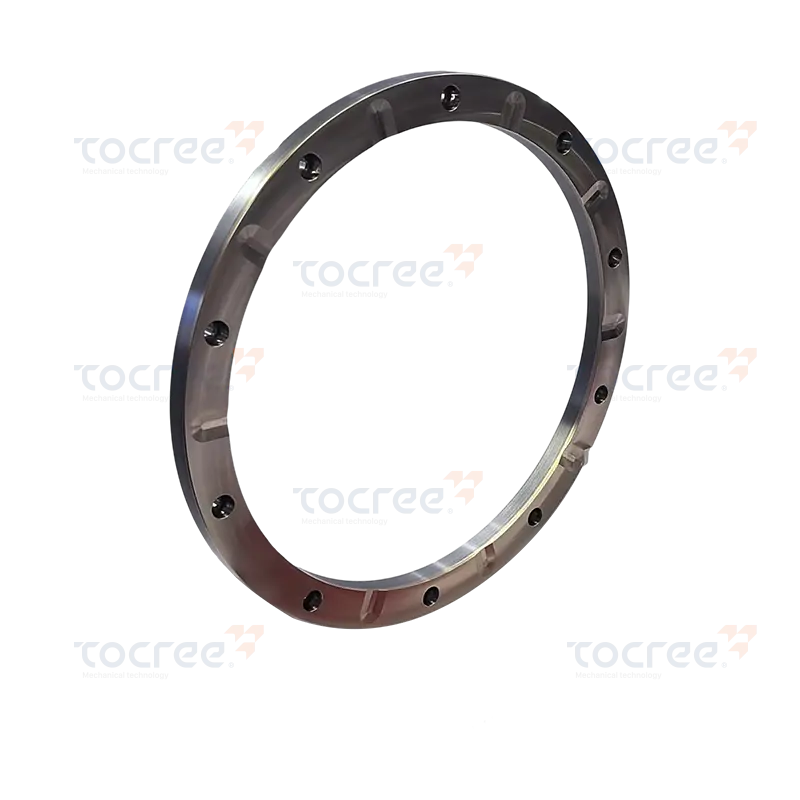
عربىThe Copper-Steel Bimetal Thrust Plate is a high-performance component designed for demandi...
Composite Class Series
-
-
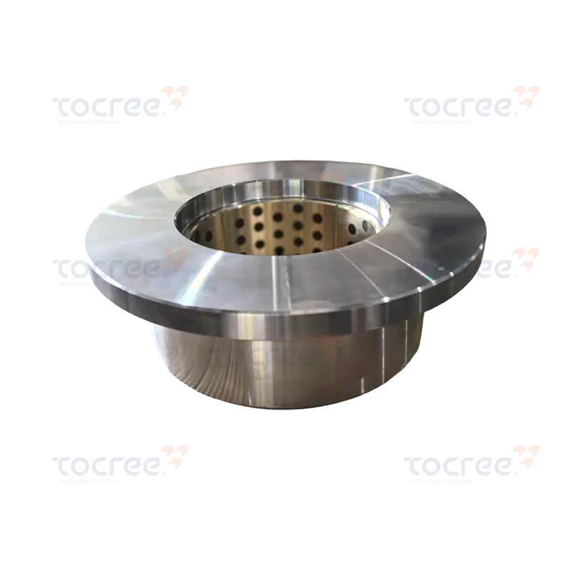 Copper-Steel Flanged Bushing
The Bronze-Steel Flanged Bushing combines the benefits of SCM435 alloy steel and high-stre...
-
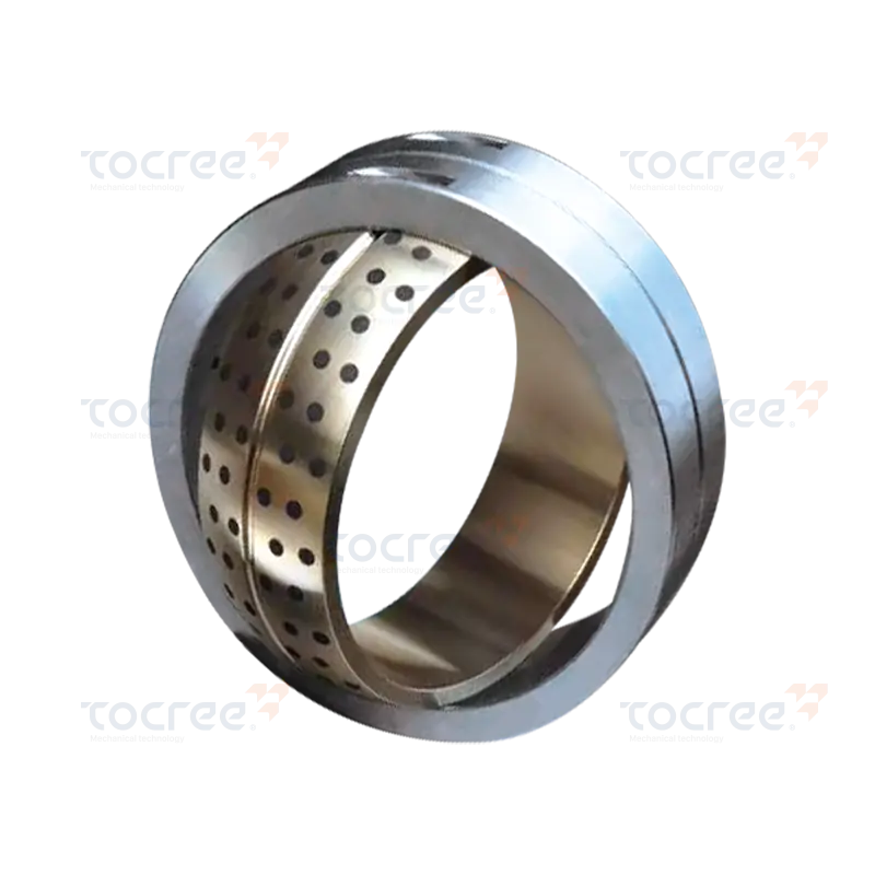 Bimetal Self-Lubricating Spherical Bearing
This Bimetal Self-Lubricating Spherical Bearing is engineered for high performance and dur...
-
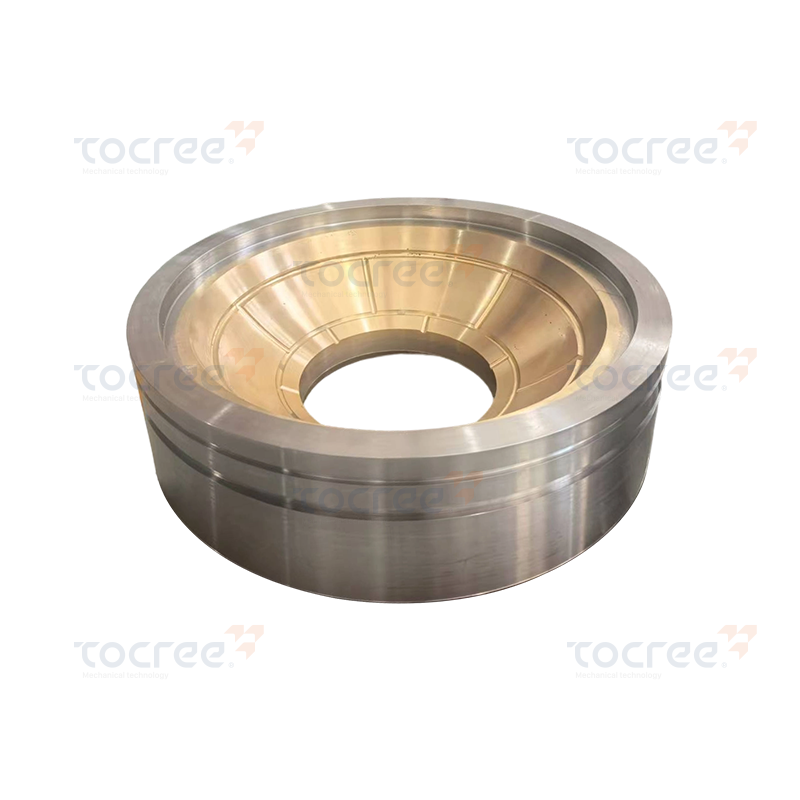 Bronze-Steel Spherical Bushing
The Bronze-Steel Spherical Bushing is made of 42CrM04 alloy steel and high-strength brass,...
-
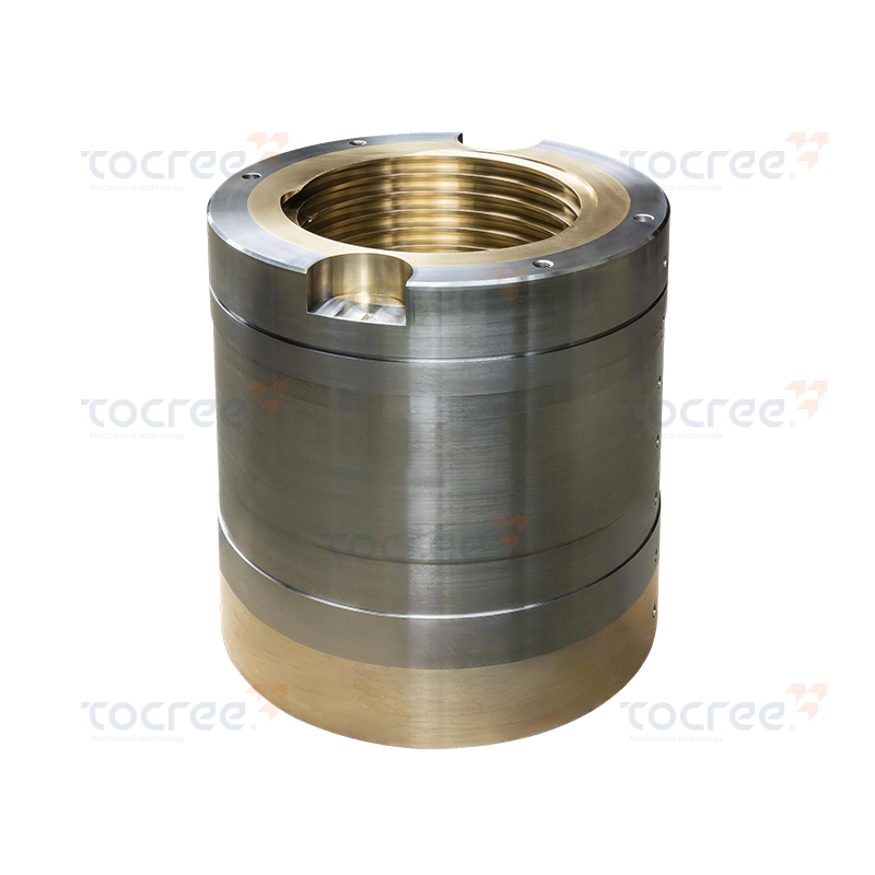 Large bimetallic threaded bushing
Structure and Materials The exterior features a high-strength carbon steel or alloy steel...
Composite Class Series products are sintered using low carbon steel and copper alloy materials, featuring high strength, high load capacity, excellent wear resistance and anti-seizing properties, making them very suitable for medium speed medium load, low speed high load and high impact load conditions. Oil grooves and oil pockets can be designed on the copper alloy surface as needed to improve lubrication effects, quickly forming an oil film to enhance service life. Typical applications: automotive industry, construction machinery, general machinery, etc.
WHO ARE WE
A Professional Copper Alloy Casting Company Integrating Casting And Precision Machining
+ contact us
Founded in 2007, Jiashan Tocree Machinery Co., Ltd. covers an area of about 30000 square meters and has a registered capital of 11 million yuan. It is located at No. 18, Zhensheng Road, Weitang Sub-district,Jiashan County Zhejiang Province, China, enjoying a superior geographical location and convenient transportation.
With rich experience in the production and processing of non-standard parts and precision machining, it is a research and development-oriented manufacturing enterprise integrating research and development, sales, design and processing. As Copper-Steel Bushing Suppliers and Copper-Steel Bushing Bearing Company in China, The company is well-equipped and has extensive experience, committed to producing finished steel sleeves, copper sleeve plates (including special-shaped parts) and copper products of various sizes, shapes and materials.
It specializes in the production of copper mining machinery parts made of various copper alloys (phosphor bronze, tin bronze, aluminum bronze, beryllium bronze). The products are widely used in metallurgical machinery, ships, mining machinery, engineering machinery, agricultural machinery, large construction machinery, large packaging machinery and mold industries.
We have copper sleeves as large as 1.5-2 meters; copper sliding plates as long as 4 meters, 400mm wide and 100mm thick; and other mechanical copper parts, such as copper nuts, copper gears, copper sleeve worm wheels, rollers and other mechanical accessories. The company is well-equipped, with its own copper smelting furnace and centrifuge, etc. It specializes in the production of copper materials of various types, with an annual output of 2300 tons. It provides copper raw material billets for our company and is a one-stop manufacturer from raw materials to finished products. Provide Custom Bimetallic Bushing for Automotive/Construction Machinery.
The company has a high-quality and strong technical team, sophisticated mechanical processing equipment, and is equipped with precise testing and experimental equipment. For a long time, the company has adhered to the market-oriented business policy, insisting on "providing high-quality services for customers, based on development and innovation, and strengthening is the last word". Guided by market-demanded products, on the road of continuous innovation and progress, good market demand is the foundation of the company's survival. With the company's current advantages, it serves customers' needs and achieves the goal of win-win cooperation and common development.

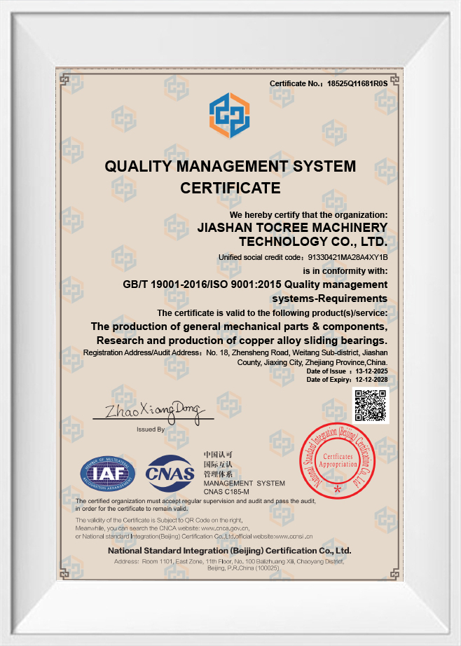
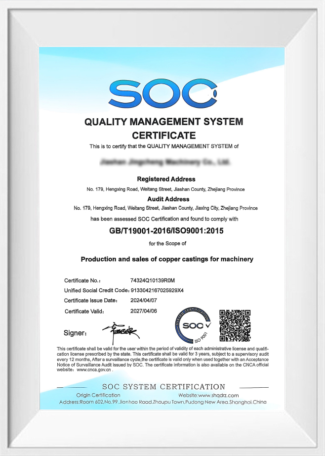
Certificate Of Honor
News
-
Anyone who has crawled under a machine with a grease gun knows the feeling: the fittings sit in the worst possible place, and the maintenance schedule never quite matches producti...
READ MORE -
Anyone who has spent time on a plant floor knows that wear rarely announces itself. It shows up as a machine that slowly stops holding tolerance, a guide that needs shimming every...
READ MORE -
Visit us at Booth AJ34, November 18–21, 2026 Jiashan, Zhejiang, China – October 2026 – Jiashan Tocree Machinery Co., Ltd. (Tocree Machinery) today announced that it will participat...
READ MORE -
Invitation to SHIPTEC China 2026 We are pleased to announce that Jiashan Tocree Machinery Co., Ltd. will exhibit at the 17th International Shipbuilding, Marine Equipment and Offsho...
READ MORE -
A copper alloy curved slider is a small part with a large job. It is the arc-shaped bronze or brass block that rides along a curved guideway, takes the load, and keeps two moving ...
READ MORE
Industry Knowledge
Why Copper Layer Thickness Matters More Than Most Buyers Realize
When people evaluate a Copper-Steel Bushing, they often focus on outer diameter and length, but the thickness of the copper alloy layer is what actually determines how the part performs under load. A layer that is too thin wears through quickly and exposes the steel backing, which accelerates shaft scoring. A layer that is too thick adds unnecessary cost and can reduce the mechanical rigidity contributed by the steel base. In our own production, we typically control the copper alloy layer between 0.3mm and 1.2mm depending on the application, and we adjust this ratio based on the expected PV value (pressure multiplied by velocity) of the customer's equipment.
A practical way to think about this is that the copper layer is the sacrificial, lubricating surface, while the steel layer is the structural skeleton. Getting the ratio wrong in either direction shortens service life, so we always ask customers for their load range and rotational speed before finalizing the layer thickness rather than defaulting to a standard spec.
Choosing the Right Steel Backing Grade for a Copper-Steel Bushing Bearing
The steel backing in a Copper-Steel Bushing Bearing is not just a generic support ring; different steel grades affect fatigue resistance, heat dissipation, and dimensional stability under thermal cycling. Low-carbon steel is the most common choice because it bonds well with copper alloys during casting or sintering and offers predictable elongation. For heavy-impact applications such as mining crushers, we sometimes recommend a slightly higher carbon content to improve fatigue strength, as long as the bonding process is adjusted to compensate for reduced ductility.
| Steel Backing Type | Typical Use | Key Advantage |
| Low-carbon steel | General industrial machinery | Good bonding, easy machining |
| Medium-carbon steel | Mining and construction equipment | Higher fatigue resistance |
| Alloy steel | High-temperature or corrosive environments | Better dimensional stability |
Because we melt and cast our own copper billets and control the bonding process on our own equipment, we can pair the steel grade and copper alloy more precisely than a supplier that outsources either half of the composite.
Common Failure Modes in Bimetallic Bushings and How to Read Them
Adhesive Wear
Adhesive wear happens when lubrication breaks down and metal-to-metal contact causes localized welding and tearing on the copper surface. It usually shows up as streaky, torn patterns rather than uniform polishing, and it often points to insufficient oil film thickness rather than a defect in the bushing itself.
Fatigue Cracking
Fatigue cracking appears as fine, web-like cracks in the copper layer, usually near the loaded zone. This is typically caused by cyclic overloading beyond the alloy's fatigue limit, and switching to a higher-strength copper alloy such as aluminum bronze can often resolve it.
Interfacial Debonding
Debonding between the copper layer and steel backing is one of the more serious failure modes because it usually indicates a manufacturing defect rather than an operating issue. It often traces back to insufficient bonding temperature or contamination during casting, which is why we run ultrasonic bond-quality checks on our finished sleeves before they leave our facility.
Sintering vs. Casting: Two Manufacturing Routes for Composite Bushings
There are two dominant ways to produce a Composite Bushing, and each affects the microstructure differently. Casting involves pouring molten copper alloy directly onto a prepared steel strip or sleeve, which produces a denser copper layer with fewer internal voids. Sintering, on the other hand, presses copper alloy powder onto the steel backing and heats it below the melting point, creating a slightly porous structure that can retain lubricant internally.
- Cast composite bushings generally offer higher load capacity and are preferred for heavy machinery joints.
- Sintered composite bushings retain oil within surface pores, which benefits applications with limited or intermittent lubrication.
- Casting requires tighter temperature control to avoid porosity defects at the bonding interface.
- Sintering is often more economical for very large batch sizes of standard dimensions.
We primarily use the casting route in our own workshop because most of the customers we work with, particularly in metallurgical and mining machinery, need the higher load-bearing capacity that a cast copper layer provides.
Matching Bushing Clearance to Real Operating Conditions
Clearance between a bushing and its shaft is frequently treated as a fixed value pulled from a catalog, but it should really be calculated based on operating temperature and expected thermal expansion. Copper alloys expand more than steel under heat, so a bushing that fits perfectly at room temperature may seize once the equipment reaches operating temperature. For applications running above 80°C continuously, we usually recommend increasing radial clearance by an additional 0.02mm to 0.05mm per 25mm of shaft diameter, though the exact figure depends on the specific copper alloy used.
Dust and particulate exposure also affects the ideal clearance. In open-air construction or agricultural machinery, slightly larger clearance combined with a scraper-style seal often outperforms a tight-fit design, since it allows contaminants to pass through rather than embedding into the copper surface.
Surface Treatments That Extend the Life of a Copper-Steel Bushing
Beyond the base alloy selection, several surface treatments can meaningfully extend service life without changing the core design of a Copper-Steel Bushing. Phosphating the steel backing before bonding improves corrosion resistance in the transition zone. Applying a thin tin or lead-free anti-friction coating over the copper surface can reduce the initial break-in period, which is especially useful in applications where the equipment cannot be gradually run in under light load.
| Treatment | Primary Benefit |
| Phosphating | Corrosion resistance at bonding interface |
| Anti-friction overlay | Shorter break-in period |
| Oil-groove machining | Improved lubricant distribution |
Oil groove pattern is another detail worth customizing rather than defaulting to a straight or spiral groove. For low-speed, high-load applications like large construction machinery, a herringbone groove pattern distributes lubricant more evenly across the loaded zone. Since we handle both raw copper smelting and final precision machining in-house, we can cut custom groove patterns to match the specific motion profile of a customer's equipment rather than limiting them to standard catalog options.
Copyright © 2025 Jiashan Tocree Machinery Co., Ltd. All Rights Reserved.
Copper-Steel Bushing Bearing Company
