 English
 中文简体
中文简体 Deutsch
 عربى
عربىFor any questions and feedback from customers, we will reply patiently and meticulously.
This aluminum alloy frame is specially designed to meet the application requirements of the vehicle....
A self-lubricating sleeve — also referred to as a self-lubricating sleeve bearing, self-lube bushing, or maintenance-free plain bearing — is a cylindrical bearing component that provides a low-friction sliding interface between a rotating or oscillating shaft and its housing without requiring an external supply of oil or grease during operation. The lubricating function is built into the bearing material itself: either through a solid lubricant phase embedded within the bearing matrix, through a porous structure impregnated with oil that releases lubricant to the contact surface under load and temperature, or through an inherently low-friction polymer surface that requires no conventional lubricant at all.
The operating principle distinguishes self-lubricating sleeves fundamentally from conventional hydrodynamic or hydrostatic plain bearings, which depend on a continuous external oil supply to maintain the lubricating film that separates shaft and bearing surfaces. A self-lubricating sleeve operates in boundary lubrication or dry friction regimes where the lubricant film is intermittent or absent — and the bearing material's composition is engineered to provide adequate load capacity, acceptable wear rate, and low friction under those severe conditions. This makes self-lubricating sleeves particularly valuable in applications where external lubrication is inaccessible, impractical, prohibited by hygiene or contamination requirements, or simply not worth maintaining across the product's lifetime.
Self-lubricating sleeve bearings are not a single product category but a family of different materials and construction approaches, each with a distinct lubrication mechanism, performance envelope, and best-fit application profile. Understanding the differences between the main types is the starting point for any serious selection process.
Sintered bronze self-lubricating sleeves — often called oilite bearings or oil-impregnated bushings — are made by compressing and sintering bronze powder into a porous structure that is then vacuum-impregnated with lubricating oil, typically to 15–30% of the bearing's volume. During operation, the combination of heat generated at the shaft-bearing interface and the pumping action of shaft rotation causes oil to migrate from the bearing's interior pores to the sliding surface, forming a lubricating film. When the shaft stops and the bearing cools, the oil is reabsorbed by capillary action into the porous matrix. This self-replenishing cycle can sustain lubrication for years of intermittent service without re-lubrication, and the oil reservoir within the bearing is effectively the bearing's entire service life lubricant supply. Sintered bronze sleeves are the most widely used self-lubricating sleeve type globally, found in electric motors, household appliances, agricultural equipment, automotive accessories, and light industrial machinery.
Solid lubricant inlay sleeves use a metallic bearing body — typically cast bronze, steel, or iron — with precisely bored recesses or through-holes filled with solid lubricant plugs, usually graphite, PTFE, or molybdenum disulfide (MoS₂) compounds. As the shaft rotates or oscillates against the bearing bore, the solid lubricant plugs wear progressively, transferring a thin, adherent layer of lubricant to both the shaft surface and the bearing bore. This transferred lubricant film reduces friction and wear between the contact surfaces without requiring any liquid or grease. Solid plug self-lubricating sleeves operate effectively at temperatures that would degrade oils and greases — graphite-plugged bronze sleeves function up to 400°C in some applications — and are used in demanding environments including high-temperature industrial furnaces, glass manufacturing equipment, outdoor agricultural machinery exposed to rain and dirt, and food processing equipment where oil or grease contamination of product is prohibited.
Polymer-based self-lubricating sleeves use materials such as PTFE (polytetrafluoroethylene), PEEK, nylon, acetal, and various fiber-reinforced composites that have inherently low friction coefficients (PTFE has a static friction coefficient as low as 0.04) and generate a self-lubricating transfer film on the mating shaft surface through the initial wear-in process. Wrapped PTFE-lined sleeves — in which a thin-wall PTFE composite liner is bonded to a steel or bronze shell — are particularly widely used in automotive suspension bushings, control arm pivots, aircraft control linkages, and precision instrumentation pivots. The PTFE liner provides a consistent low-friction, no-stick sliding surface that maintains performance across a wide temperature range (typically -200°C to +260°C for pure PTFE), operates without any lubricant, and tolerates oscillating and reversing loads that would cause a hydrodynamic bearing to fail immediately due to insufficient film formation.
Bimetal and multilayer self-lubricating sleeve bearings combine a steel backing for structural strength with a bearing alloy interlayer (typically leaded bronze or tin-bronze) and a thin overlay of polymer composite — most commonly a PTFE-lead mixture, PTFE-fiber composite, or acetal compound — that provides the low-friction sliding surface. The multilayer construction allows each layer to be optimized for a different function: the steel back provides press-fit retention and load distribution, the sintered bronze interlayer provides good bonding and moderate conformability, and the PTFE composite overlay provides the self-lubricating sliding surface. DU-type and DX-type bearings (commercial designations for widely used multilayer self-lubricating sleeve specifications) are the dominant component in automotive engine small-end bushings, agricultural machinery pivot pins, construction equipment pin joints, and high-cycle industrial linkages where the combination of high load capacity, low friction, and maintenance-free operation is required in a compact envelope.
The table below summarizes the four main self-lubricating sleeve types across the most practically important selection criteria, providing a quick-reference framework for initial technology selection.
| Type | Lubrication Mechanism | Max Temp (°C) | Load Capacity | Best Application |
| Sintered bronze (oil-impregnated) | Oil migration from porous matrix | 100–120°C | Moderate | Motors, appliances, light machinery |
| Solid lubricant plug (graphite/MoS₂) | Transfer film from plug wear | Up to 400°C | High | Furnaces, food processing, outdoor equipment |
| PTFE / polymer composite | Low-friction transfer film on shaft | 260°C (PTFE) | Low–Moderate | Aerospace, medical, oscillating linkages |
| Multilayer (DU/DX bimetal) | PTFE composite overlay transfer film | 130–180°C | High | Automotive, construction equipment, pivots |
Self-lubricating sleeve bearing datasheets present a set of performance parameters that, if misunderstood or misapplied, lead directly to premature bearing failure. Understanding what each parameter represents and how they interact is essential for confident bearing selection.
The PV value — the product of bearing pressure P (in MPa or N/mm²) and sliding velocity V (in m/s) — is the fundamental operating parameter for self-lubricating sleeve bearings. PV represents the rate at which frictional heat is generated at the bearing surface per unit area: high pressure with high speed generates more heat than the same pressure at low speed. Every self-lubricating sleeve material has a maximum permissible PV value above which the heat generation rate exceeds the bearing's ability to dissipate it, causing the bearing surface temperature to rise to the point where the lubricant degrades, the bearing material softens or deforms, and wear rate accelerates to failure. Importantly, the maximum permissible PV is not achieved at any combination of P and V that produces that product — there are also separate maximum pressure limits (P_max) and maximum velocity limits (V_max) that constrain the operating envelope independently of the PV product. A bearing may have a PV limit of 0.1 MPa·m/s, a P_max of 40 MPa, and a V_max of 0.5 m/s — and all three constraints must be satisfied simultaneously.
The friction coefficient of a self-lubricating sleeve bearing is not a fixed constant — it varies with sliding velocity, contact pressure, temperature, the roughness of the mating shaft, and the state of the transfer film on the shaft surface. Published friction coefficient values in datasheets (typically 0.03–0.2 depending on material type) represent steady-state values under representative conditions after initial run-in, not instantaneous or worst-case values. The start-up friction coefficient — before the transfer film is established or before the oil has migrated to the bearing surface — is typically two to five times higher than the steady-state value. This is particularly important for applications with very tight torque budgets (precision instruments, actuators with small drive motors) and for applications with frequent start-stop cycles where steady-state film conditions are never fully established.
The mating shaft's surface condition has a major influence on self-lubricating sleeve bearing performance and life. For metallic self-lubricating sleeves (sintered bronze, solid plug bronze), the shaft should be hardened to at least 30 HRC to prevent the shaft surface from being abraded by the bronze bearing material, which is typically harder than annealed steel shafting. A soft shaft running in a bronze self-lubricating sleeve will accumulate bronze debris transferred onto the shaft, progressively increasing friction and wear until failure. For PTFE composite and multilayer sleeve bearings, the shaft surface hardness requirement is less stringent (20 HRC is typically adequate) because the PTFE overlay is softer and conforms to minor shaft irregularities, but shaft surface roughness must be controlled to Ra 0.4–0.8 µm — too rough, and abrasive asperities cut through the thin PTFE overlay quickly; too smooth (below Ra 0.1 µm), and the transfer film has insufficient mechanical anchor points to adhere reliably to the shaft surface.
Self-lubricating sleeve bearings are not universally superior to conventional oil or grease-lubricated bearings — they have lower maximum PV limits and higher friction coefficients than well-lubricated plain bearings operating in the hydrodynamic regime. Their advantage is decisive, however, in a specific set of conditions where conventional lubrication fails or is impractical.
The choice between a self-lubricating sleeve bearing and a rolling element bearing (ball or roller bearing) is one of the most common design decisions in mechanical engineering, and each technology has genuine advantages in specific conditions. Neither is universally superior, and the decision should be made by comparing the specific requirements of the application against each technology's strengths.
| Criteria | Self-Lubricating Sleeve | Rolling Element Bearing |
| Starting friction | Higher (boundary lubrication) | Very low (rolling contact) |
| Vibration and shock load tolerance | Excellent (large contact area) | Moderate (point/line contact) |
| Noise and vibration generation | Very low (silent operation) | Low to moderate (race noise) |
| Radial space requirement | Minimal (thin wall) | Larger (cage and rolling elements) |
| Maintenance requirement | None (maintenance-free) | Periodic re-lubrication or sealed |
| High-speed performance | Limited (heat generation) | Excellent |
| Cost | Low to moderate | Moderate to high |
| Oscillating / low-speed motion | Excellent | Poor (false brinelling risk) |
| Contamination tolerance | Good (solid construction) | Poor (particle ingress damages races) |
Selecting a self-lubricating sleeve bearing requires working through the application's operating conditions systematically and matching them against the performance limits of candidate bearing types and materials. Jumping directly to a specific product based on superficial similarity to a previous application — without confirming the PV, temperature, and environmental compatibility — is the most common route to premature bearing failure.
Calculate the bearing pressure P by dividing the radial load (in Newtons) by the projected bearing area (bore diameter × length, in mm²), converting to MPa. Calculate the sliding velocity V in m/s from the shaft rotational speed and diameter, or the stroke length and cycle rate for oscillating applications. Determine whether the motion is continuous rotation, intermittent rotation, oscillating, or reciprocating — this affects both the PV calculation (oscillating motion has a lower effective PV than continuous rotation at the same peak velocity) and the type of self-lubricating sleeve best suited. Check both the calculated PV product and the individual P and V values against the bearing material's limits, and ensure all three constraints are satisfied with a safety factor of at least 1.5–2.0 to account for load and speed variations in service.
Determine the operating temperature range — both ambient and the bearing's own operating temperature, which will be higher than ambient due to frictional heat generation. Cross-reference this against the temperature limits of candidate bearing materials: standard oil-impregnated sintered bronze is limited to approximately 80–120°C continuous; PTFE composite multilayer bearings operate to 130–180°C; graphite-inlay bronze sleeves handle up to 400°C. Identify any chemical exposure — acids, alkalis, solvents, water, food-grade cleaners — and verify material compatibility. Polymer self-lubricating sleeves are often more chemically resistant than metallic types, but specific polymer grades must be checked against the actual chemicals present, as chemical resistance varies significantly between polymer types.
Self-lubricating sleeve bearings require a specific radial clearance between the bearing bore and the shaft diameter for correct operation. Too little clearance causes the bearing to grip the shaft, generating excessive friction and heat that rapidly destroys both shaft and bearing. Too much clearance allows the shaft to rock within the bore under load, creating edge loading at the bearing ends and dynamic impact loads that cause accelerated wear and fatigue. Recommended bore clearances for self-lubricating sleeve bearings are typically larger than those used for rolling element bearings — sintered bronze sleeves typically use H7/f7 or H8/f7 fit (clearance of 0.01–0.05mm on small diameters), while PTFE composite sleeves may require slightly tighter fits due to the polymer overlay's tendency to cold-flow under sustained high contact pressure.
Self-lubricating sleeves are among the simplest bearings to install correctly — but incorrect installation is also surprisingly common and results in early failure that is often incorrectly attributed to the bearing material rather than the installation method.
Self-lubricating sleeves are wear components — they have a finite service life determined by the operating conditions, the bearing material's wear resistance, and the surface condition of the mating shaft. Unlike rolling element bearings, which often fail with a sudden, dramatic increase in noise and vibration, self-lubricating sleeve bearings fail gradually through progressive wear that increases shaft-to-bore clearance until it reaches an unacceptable level. This gradual failure mode is predictable and manageable if monitored correctly, but can be missed entirely if no monitoring is in place, eventually resulting in shaft damage, excessive vibration, and damage to other system components.
The primary indicator of self-lubricating sleeve wear is increased shaft-to-bore clearance, measured by inserting a feeler gauge between shaft and bearing bore or by measuring shaft displacement with a dial indicator under a defined test load. Most bearing manufacturers specify a maximum permissible clearance — typically two to three times the original running clearance — beyond which the bearing should be replaced. In practice, the replacement criterion is often set by the system's tolerance for shaft movement: in precision instrumentation, a clearance increase of 0.02mm may be unacceptable; in a large agricultural pivot joint, 0.5mm of additional clearance may be tolerable.
Visual inspection of removed self-lubricating sleeves provides valuable diagnostic information about whether the bearing was operating within its design limits. Uniform wear across the full bearing length and a polished, smooth bore surface indicate correct operation and proper shaft alignment. Heavy wear concentrated at one end of the bearing indicates shaft misalignment or deflection under load. Scored or grooved bearing surfaces indicate abrasive contamination entering the bearing clearance, pointing to inadequate sealing. Overheated or discolored bearing material — darkening, cracking, or delamination of a PTFE layer — indicates operation above the material's temperature limit, requiring investigation of whether the PV limit was exceeded or whether the housing's heat dissipation was inadequate for the application.
This aluminum alloy frame is specially designed to meet the application requirements of the vehicle....
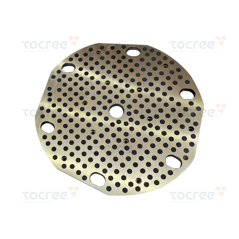
Material structure: Cast aluminum brass CuZn25Al6Fe3Mn3, with graphite insert. Application features:...
High tensile strength: The tensile strength of this product reaches up to 750N/mm², ensuring excelle...
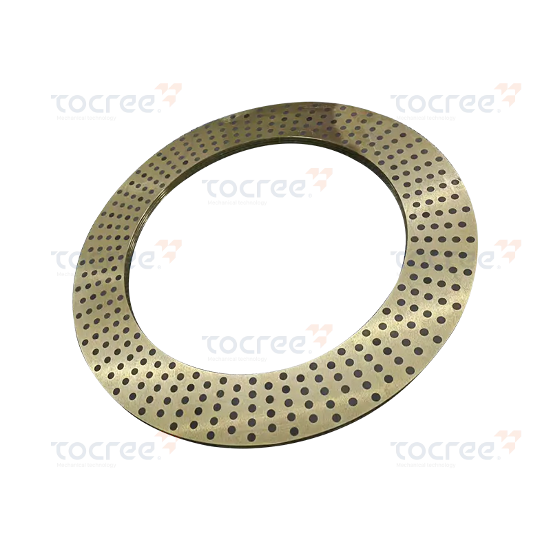
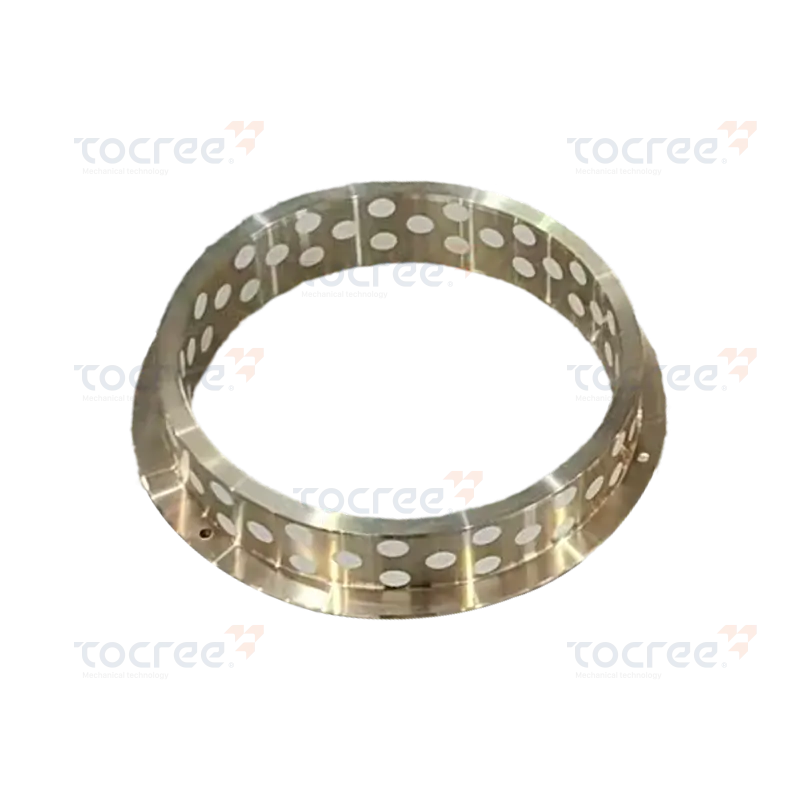
Solid self-lubricating copper rings are high-performance components, made by precision machining wit...
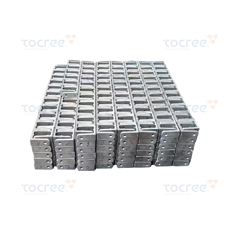
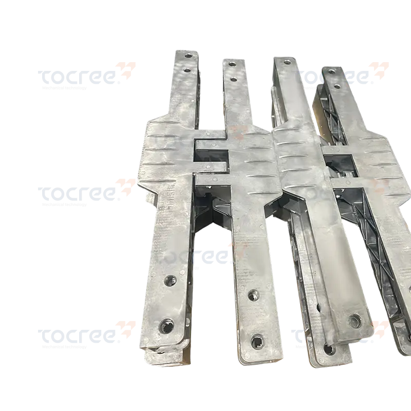
This aluminum alloy fixing block is made from 6063 aluminum alloy as the base material. After T5 hea...
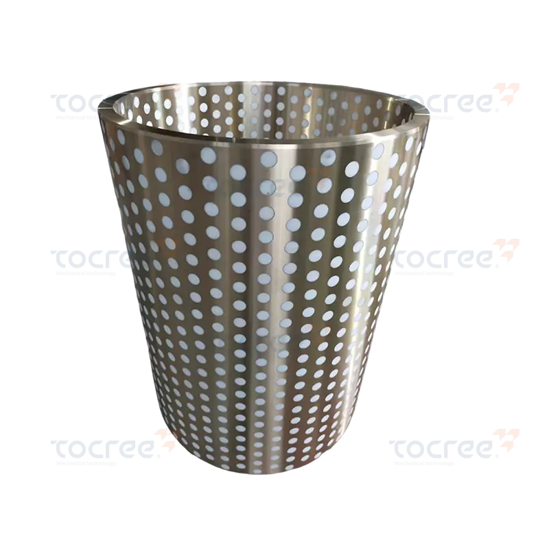
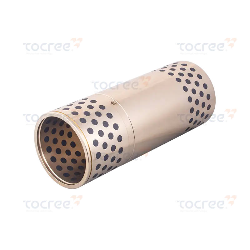
This solid self-lubricating copper sleeve embedded with PTFE combines the wear resistance of brass w...
Copyright © 2025 Jiashan Tocree Machinery Co., Ltd. All Rights Reserved.
Customized Copper Alloys Machinery Parts
