

 English
 中文简体
中文简体 Deutsch
 عربى
عربىFor any questions and feedback from customers, we will reply patiently and meticulously.
Material structure: Cast aluminum brass CuZn25Al6Fe3Mn3, with graphite insert. Application features:...
A flanged self-lubricating bearing is a plain bearing — meaning it uses a sliding contact surface rather than rolling elements — that incorporates an integral flange at one end of the cylindrical bore. The flange serves as a built-in axial locating feature and thrust face, preventing the bearing from being pushed through its housing in one direction and allowing it to carry combined radial and axial loads simultaneously. The self-lubricating aspect means the bearing is designed to operate without external grease or oil supply, drawing instead on solid lubricants embedded in or applied to its sliding surface to maintain a continuous, low-friction interface between the bearing bore and the shaft running inside it.
This combination of features — flange location and maintenance-free lubrication — makes flanged self-lubricating bearing exceptionally practical across a wide range of industrial, agricultural, and mechanical applications. They eliminate the need for grease nipples, lubrication schedules, and the associated maintenance labor. They simplify housing design by removing the need for separate thrust washers or snap rings to retain the bearing axially. And because they operate dry or near-dry, they perform reliably in environments where conventional lubricated bearings struggle: dusty, wet, high-temperature, food-grade, or hard-to-access locations where regular relubrication is impractical or prohibited.
The self-lubricating mechanism in these bearings works differently depending on the specific material construction, but the underlying principle is consistent: the bearing material continuously releases or presents a lubricating film at the sliding interface, reducing friction and wear without any external lubricant input from the operator or maintenance system.
Sintered porous bronze flanged bearings are manufactured by compacting and sintering bronze powder to create a bearing with a controlled network of interconnected pores throughout its structure. These pores are then vacuum-impregnated with lubricating oil — typically ISO VG 68 or VG 100 mineral oil — which is held within the porous matrix by capillary action. As the shaft rotates inside the bearing, frictional heat and the pumping action of the shaft surface draw oil out of the pores to the sliding interface, forming a lubricating film. When the bearing cools and shaft rotation stops, the oil is drawn back into the pores by capillary action. This self-replenishing cycle continues throughout the bearing's service life, with the oil reservoir providing years of maintenance-free operation in lightly to moderately loaded applications.
Multi-layer composite flanged self-lubricating bearings use a different mechanism. The most common construction consists of a steel backing for structural strength, a sintered bronze interlayer that provides mechanical bonding, and a thin surface layer of PTFE (polytetrafluoroethylene) compound — typically PTFE blended with lead, bronze powder, or other fillers — as the sliding face. PTFE has an exceptionally low coefficient of friction (around 0.04–0.20 depending on load and speed conditions) and acts as a solid lubricant: as the shaft slides against the PTFE surface layer, microscopic transfer film forms on the shaft, creating a matched pair of low-friction surfaces that sustain themselves through the running process. This mechanism requires no liquid lubricant at all, making these bearings true dry-running components suited to applications where any oil contamination is unacceptable.
Some flanged self-lubricating bearings — particularly those used in high-temperature or heavy-load applications — use solid lubricant plugs or inlays of graphite or molybdenum disulfide (MoS₂) embedded directly into a bronze or cast iron body. As the shaft rotates, the plugs are gradually worn, continuously depositing solid lubricant onto the shaft surface and the bearing bore. Graphite is particularly effective at high temperatures where oil-based lubricants would oxidize or evaporate, making graphite-plugged flanged bearings a common choice in furnace equipment, kiln car guides, and high-temperature conveyor systems.
The performance capabilities and appropriate application environment of a flanged self-lubricating bearing are largely determined by the material system used in its construction. The main categories available differ significantly in load capacity, speed rating, temperature range, and chemical resistance.
Oil-impregnated sintered bronze flanged bearings are the most widely used self-lubricating bearing type for general engineering applications. They conform to ISO 2795 and DIN 1850 standards in terms of dimensions, and they are readily available in metric and inch sizes from a wide range of manufacturers. Their typical load capacity is moderate — dynamic radial loads up to approximately 60–80 N/mm² — and they perform well at shaft speeds up to around 2–3 m/s depending on load. Operating temperature range is limited by the impregnated oil, typically −20°C to +80°C for mineral oil impregnation, with higher temperature ranges possible with synthetic oil variants. They are cost-effective, easy to machine to size, and well-understood in service.
Steel-backed composite flanged bearings — commonly known by the DU designation originating from the Glacier DU bearing developed in the 1950s — have become a global standard in maintenance-free bearing design. The steel backing provides high compressive strength, and the PTFE composite sliding layer provides very low friction and true oil-free operation. These bearings handle higher specific loads than sintered bronze — up to 250 N/mm² static, 140 N/mm² dynamic in standard grades — and their operating temperature range is typically −200°C to +280°C, far exceeding oil-impregnated bronze. They are the standard choice for automotive components, agricultural machinery pivots, construction equipment, and any application combining high load, low-speed oscillating motion, and a requirement for zero maintenance lubrication.
Solid cast or wrought bronze flanged bearings with graphite plug inlays offer robust load-carrying capacity combined with self-lubricating performance at elevated temperatures. Common bronze alloys used include CuSn8, CuSn12, and CuAl10Fe3, each offering different combinations of hardness, wear resistance, and corrosion resistance. The graphite plugs are pressed into pre-drilled holes in the bronze body at regular intervals across the bearing surface, covering approximately 20–30% of the sliding area. These bearings are well-suited to slow-moving heavy machinery, water-lubricated applications, and high-temperature environments where the bronze body's thermal conductivity helps dissipate frictional heat.
Engineered polymer flanged bearings — made from materials such as IGLIDUR compounds (igus), PEEK, Nylon (PA), or acetal (POM) with integrated lubricant additives — offer unique advantages in applications requiring electrical insulation, corrosion immunity, very low weight, or operation in chemically aggressive media. High-performance polymer bearings based on PEEK can operate at continuous temperatures up to 250°C and withstand aggressive chemical environments that would attack bronze or steel-backed bearings. Their load capacity is generally lower than metallic bearing types, but their combination of non-magnetic, non-conductive, and non-corroding properties makes them irreplaceable in specific applications such as medical equipment, semiconductor manufacturing, and food processing machinery.
The table below summarizes the key performance characteristics of the main flanged self-lubricating bearing material types to help with application selection:
| Material Type | Max Load (Dynamic) | Temp. Range | Lubrication | Best For |
| Sintered Bronze (Oil) | 60–80 N/mm² | −20°C to +80°C | Oil-impregnated | General light–medium duty |
| Steel-Backed PTFE (DU) | Up to 140 N/mm² | −200°C to +280°C | Dry (PTFE film) | High load, oscillating, no-lube |
| Bronze + Graphite Plugs | 60–100 N/mm² | Up to +350°C | Graphite solid lube | High temp, slow heavy loads |
| Engineered Polymer/PEEK | 20–60 N/mm² | Up to +250°C | Dry (additive-based) | Food, chemical, electrical insulation |
The flange on a flanged plain bearing is more than just a retention feature — it is a structural element that fundamentally changes the bearing's capability compared to a plain cylindrical sleeve. Understanding what the flange does in practice helps engineers specify the right bearing configuration for their application.
The flange provides axial location of the bearing within its housing, preventing the bearing from migrating along the shaft axis under axial loading. In applications with combined radial and axial loads — such as a pivot pin that must resist both bending and thrust forces — the flange face acts as a thrust bearing surface, carrying axial loads against the housing face. The contact area of the flange face determines its axial load capacity, so larger flange diameters provide higher axial load ratings. For applications with very high or sustained axial loads, it is important to verify that the flange face contact pressure stays within the material's allowable limits — exceeding these limits causes progressive wear of the flange face and eventual loss of axial positioning accuracy.
Flanged bearings are typically specified in two flange thickness configurations: standard flange (thicker, higher axial load capacity) and thin flange (reduced flange thickness for space-constrained housing designs). Some manufacturers also offer double-flanged bearings, where a flange is present at both ends of the bore — providing axial retention in both directions without requiring a separate retaining feature. Double-flanged configurations are particularly useful in oscillating pivot applications where thrust loads may reverse direction.
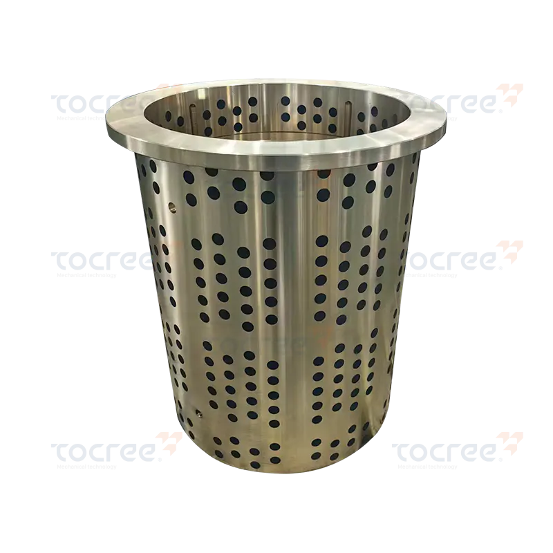
Correct sizing and fit tolerances are critical to the performance and service life of any plain bearing, and flanged self-lubricating bearings are no exception. Both the housing bore fit and the shaft-to-bore clearance must be within specified ranges for the bearing to function correctly.
Flanged self-lubricating bearings are designed to be pressed into their housings with a controlled interference fit — typically an H7/p6 or H7/r6 tolerance combination in the ISO system — that prevents the bearing from rotating in the housing under operating loads. For steel-backed composite bearings, the interference fit also helps the bearing conform to any minor irregularities in the housing bore, improving contact area and heat dissipation. The housing bore should be machined to the bearing manufacturer's specified tolerance, with good surface finish (Ra 0.8–1.6 μm typically) and correct cylindricity. An oversized housing bore results in the bearing spinning in the housing rather than on the shaft, causing rapid damage to both components. An undersized bore compresses the bearing excessively, reducing the bore diameter below spec and potentially seizing the shaft.
The running clearance between the shaft and the bearing bore is equally critical. Too little clearance causes high friction, heat buildup, and early wear failure. Too much clearance allows shaft movement that increases impact loading and surface stress. Recommended shaft tolerances for flanged self-lubricating bearings are typically h6 or f7 for rotating shaft applications and h9 or e8 for oscillating applications. After the bearing is pressed into its housing, the bore diameter will reduce slightly due to the interference fit — this press-fit reduction must be accounted for when specifying shaft diameter to ensure the final running clearance falls within the recommended range. Most bearing manufacturers provide tables showing the expected bore reduction after pressing as a function of housing interference and bearing wall thickness.
The shaft running inside a flanged self-lubricating bearing must be adequately hard and well-finished to achieve good bearing life. For steel-backed PTFE composite bearings, shaft hardness of at least 55 HRC (case-hardened or induction-hardened) is generally recommended for optimum wear performance, with surface roughness Ra 0.2–0.8 μm. Softer or rougher shafts cause accelerated abrasion of the bearing surface and reduce service life significantly. For sintered bronze bearings, somewhat softer and rougher shafts are acceptable, as the bronze material is more tolerant of shaft surface variation. Stainless steel shafts can be used but should be verified for adequate hardness, as some stainless grades are relatively soft and may themselves wear against the bearing surface.
Flanged self-lubricating bearings appear across an enormous range of industrial and mechanical applications. Their combination of integrated axial location and maintenance-free operation makes them a default choice in many design situations.
Correct installation is essential to achieving the rated performance and service life of a flanged self-lubricating bearing. Poor installation practice — particularly with steel-backed composite bearings — is one of the most common causes of premature bearing failure in the field.
Selecting the correct flanged self-lubricating bearing for a specific application requires working through a set of operating parameters systematically. Here is the practical selection process that bearing engineers follow.
Start by defining the operating conditions clearly: the radial load on the bearing (in Newtons or kilonewtons), any axial or thrust loads the flange face must carry, the shaft diameter, the type of motion (continuous rotation, oscillation, or a mix), the shaft speed or oscillation frequency, the operating temperature range, and whether any lubricant can be used or whether completely dry operation is required. With these parameters established, calculate the specific bearing pressure (load divided by projected area of bore length × diameter) and the PV value (specific pressure multiplied by sliding velocity) — this combined parameter is the standard basis for comparing operating conditions against a bearing material's capability limits.
Match these calculated values against the material capability data from the bearing manufacturer — each material type has published maximum P, V, and PV limits, above which wear rates become unacceptably high. For applications close to a material's limits, factor in any temperature rise from friction (higher PV means more heat generation) and verify that the selected material's temperature rating still provides margin. Finally, check that standard dimensional series bearings are available in the required shaft diameter — most flanged self-lubricating bearings are manufactured in standard metric series (ISO 3547 for sintered bronze, DIN 1850 for sleeve bearings) from 3 mm bore upward, with a wide selection of flange configurations available from stock.
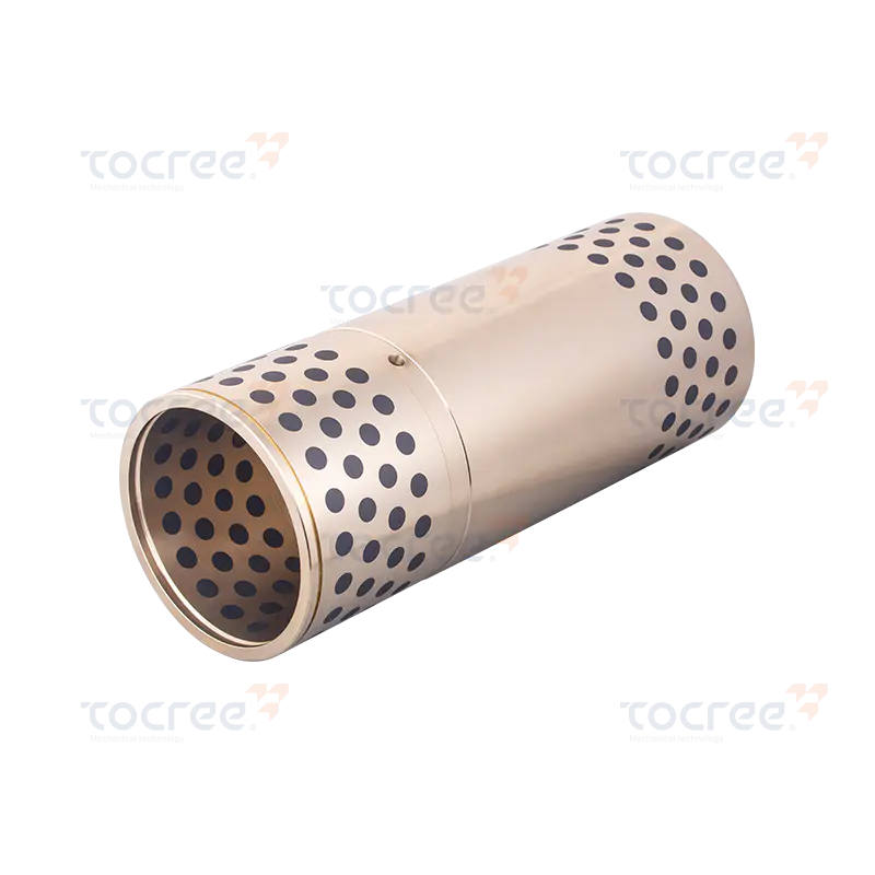
Material structure: Cast aluminum brass CuZn25Al6Fe3Mn3, with graphite insert. Application features:...
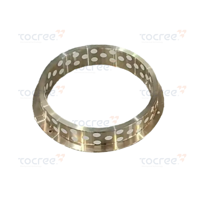
High tensile strength: The tensile strength of this product reaches up to 750N/mm², ensuring excelle...
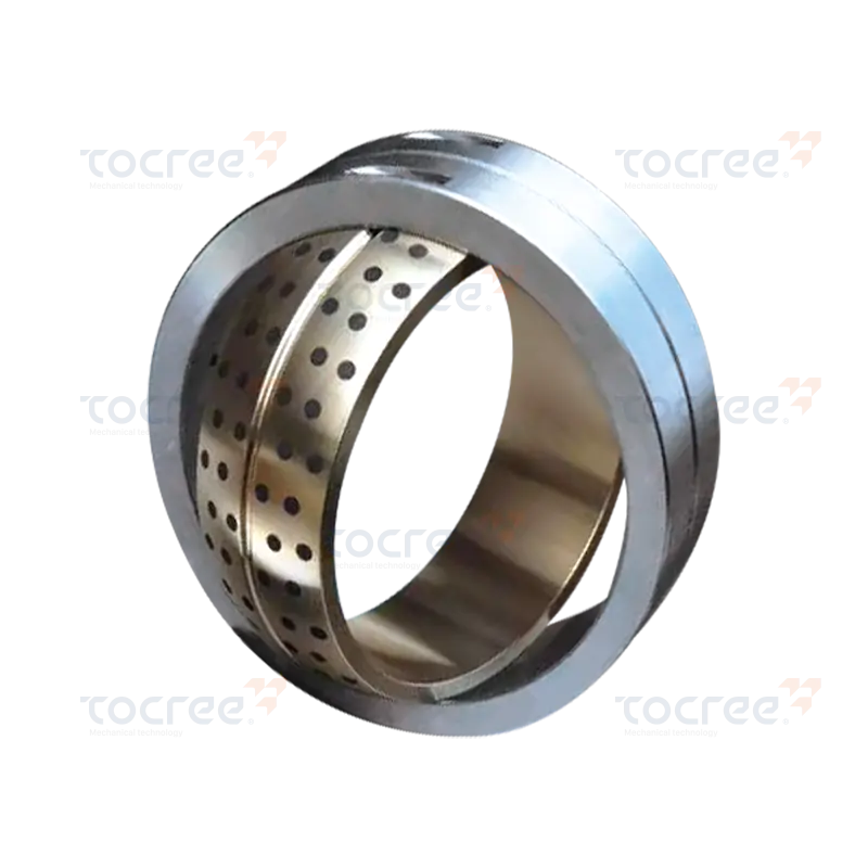
This Bimetal Self-Lubricating Spherical Bearing is engineered for high performance and durability, f...
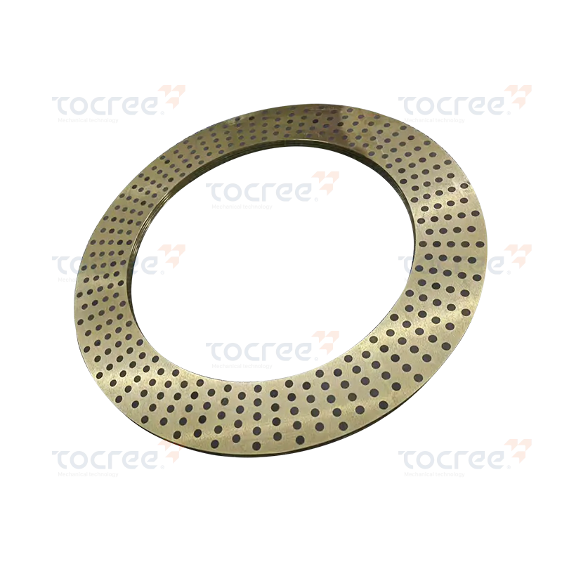
Solid self-lubricating copper rings are high-performance components, made by precision machining wit...
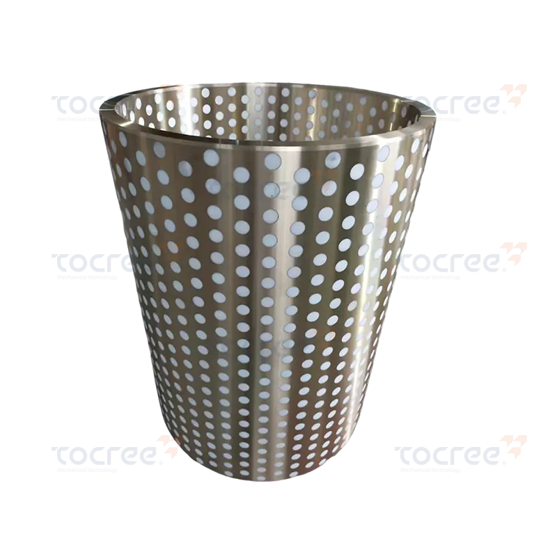
This solid self-lubricating copper sleeve embedded with PTFE combines the wear resistance of brass w...
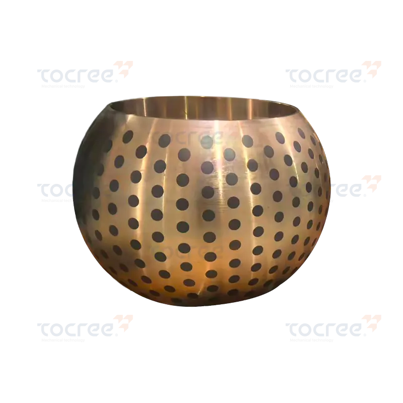
This spherical self-lubricating copper sleeve is made from high-strength high-strength brass as the ...
Copyright © 2025 Jiashan Tocree Machinery Co., Ltd. All Rights Reserved.
Customized Copper Alloys Machinery Parts
