 English
 中文简体
中文简体 Deutsch
 عربى
عربىFor any questions and feedback from customers, we will reply patiently and meticulously.
Material structure: Cast aluminum brass CuZn25Al6Fe3Mn3, with graphite insert. Application features:...
An oilless shaft sleeve — also called a self-lubricating sleeve bearing, oil-free bushing, or dry shaft sleeve — is a cylindrical bearing component designed to support a rotating or oscillating shaft without requiring any external lubrication such as grease, oil, or periodic re-greasing. The sleeve wraps around the shaft journal and provides a low-friction sliding interface between the shaft and its housing, relying entirely on solid lubricants embedded in or applied to the bearing material itself to manage friction and wear over the life of the component.
The problem that oilless shaft sleeves solve is fundamentally one of maintenance access, environmental contamination, and operational reliability. In a conventional oil-lubricated sleeve bearing, friction and wear are controlled by a continuous or periodic supply of oil or grease to the bearing interface. This works well when the bearing is accessible for routine lubrication, when the operating environment is clean and temperate, and when oil contamination of the surrounding equipment or product is not a concern. But many real-world applications fail one or more of these conditions: bearings in food processing equipment cannot be greased with petroleum lubricants; bearings deep inside large machinery structures are inaccessible for regular greasing; bearings in dusty mining environments have their oil film contaminated within days of application; bearings in high-temperature furnace conveyors operate above the decomposition temperature of any practical lubricating oil.
A properly specified oilless shaft sleeve eliminates all of these constraints. It provides the load-carrying and shaft-locating function of a conventional sleeve bearing with zero external lubrication input for the entire service life of the component — typically 5,000 to 50,000 operating hours depending on the material, load, speed, and environment. For equipment designers, this means simpler lubrication systems, lower maintenance labor costs, and the ability to install bearings in locations that would be impractical to lubricate. For end users, it means reduced downtime, eliminated lubricant procurement and waste disposal costs, and improved product cleanliness in sensitive applications.
The ability of an oilless shaft sleeve to operate without external lubrication is not simply a matter of using a low-friction material — it depends on a specific tribological mechanism by which the bearing surface actively generates and replenishes a lubricating film during operation.
The most important mechanism in self-lubricating sleeve bearings is the formation of a transfer film on the mating shaft surface. As the shaft rotates against the bearing bore, microscopic quantities of solid lubricant — typically PTFE (polytetrafluoroethylene), graphite, molybdenum disulfide (MoS₂), or combinations thereof — are released from the bearing material and adhere to the shaft surface as a thin, continuous coating typically 1–5 µm thick. Once this transfer film is established (usually within the first few hours of operation, called the "run-in" period), the contact is effectively between two lubricated surfaces — the transfer film on the shaft and the solid lubricant in the bearing bore — rather than between bare metal and bearing material. This dramatically reduces the friction coefficient (typically to 0.03–0.15 depending on the material and conditions) and wear rate for the remainder of the bearing's life.
Different oilless sleeve bearing designs release their solid lubricant through different mechanisms. In sintered metal bearings (oil-impregnated sintered bronze or iron), lubricant is released thermally — the porous metal matrix expands slightly under the heat of friction, pumping stored oil to the surface; when the bearing cools at rest, the oil is drawn back in by capillary action. In PTFE-lined composite bearings, the low surface energy of PTFE naturally causes it to smear onto the shaft surface under contact pressure. In graphite-plugged bronze bearings, the graphite inserts are pressed directly into holes or grooves in the bronze matrix, and sliding contact progressively shears off microscopic graphite particles that form the lubrication layer. In polymer matrix bearings filled with PTFE, graphite, or MoS₂, the filler particles are homogeneously distributed throughout the material and are continuously exposed at the wear surface as the bearing runs in.
Every self-lubricating oilless shaft sleeve has a limiting PV value — the product of bearing pressure P (in MPa or psi) and sliding velocity V (in m/s or ft/min) at which the bearing material can operate without overheating, excessive wear, or seizure. The PV limit is the fundamental performance boundary for self-lubricating bearings, analogous to the load rating of a rolling element bearing. When the PV value is exceeded, frictional heat generation at the interface exceeds the bearing material's ability to conduct heat away, causing thermal degradation of the solid lubricant, accelerated wear, and ultimately bearing failure. Designers must calculate the actual PV for their application (P = radial load / projected area; V = π × shaft diameter × RPM / 60,000) and confirm it is below the material's rated PV limit — typically with a safety factor of 2–3 for continuous operation.
The performance of a self-lubricating shaft sleeve is largely determined by the choice of base material and solid lubricant system. Each material type has specific strengths, limitations, and best-fit application areas. Here is a detailed overview of the main categories.
Graphite-plugged bronze oilless sleeves — sometimes called "graphite-bronze" or "maintenance-free bronze" sleeves — consist of a leaded or unleaded bronze body with cylindrical plugs of graphite or graphite-MoS₂ compound pressed into drilled holes that are regularly distributed across the bore and sometimes the end faces. The bronze provides excellent load-carrying capacity (operating pressures up to 60–80 MPa in some grades), high thermal conductivity for heat dissipation, and good dimensional stability. The graphite plugs contribute the self-lubricating function, accounting for typically 20–35% of the bearing surface area by coverage. These sleeves operate reliably up to 400°C (using carbon-graphite compounds rather than pure graphite) and are suitable for slow to moderate sliding speeds (up to approximately 2 m/s continuous). They are the most widely specified oilless sleeve bearing type for industrial machinery — conveyors, presses, hoists, injection molding machines, and general manufacturing equipment — because of their combination of high load capacity, wide temperature range, and robustness to contaminated environments.
PTFE-lined composite oilless sleeves (commonly known under trade names such as DU® by Oiles, DP4® by SKF/Glacier, or similar products from Igus and Permaglide) consist of a steel backing, a porous bronze interlayer (typically sintered to the steel), and a PTFE-lead or PTFE-fiber composite sliding layer 0.01–0.03 mm thick bonded to the bronze. The steel backing provides press-fit retention in the housing bore, the bronze interlayer anchors the PTFE layer mechanically, and the PTFE surface layer provides an exceptionally low coefficient of friction (0.03–0.12 under typical loads) and excellent chemical resistance. This construction achieves an optimal balance of very low friction, compact cross-section (wall thickness as thin as 0.7–1.5 mm, allowing use in space-constrained applications), high load capacity (up to 250 MPa static), and good heat conduction through the steel back. PTFE composite sleeves are the standard choice for automotive applications (pedal pivot bearings, seat rail guides, door hinge pivots), agricultural machinery, and general mechanical engineering where a thin, self-lubricating bearing is needed in a precision housing. Their primary limitation is a moderate temperature ceiling (continuous operation up to 120–150°C for lead-free variants) and sensitivity to shock loads that can delaminate the PTFE layer.
Sintered bronze sleeve bearings are manufactured by pressing and sintering bronze powder into a porous structure with 20–35% void volume, then vacuum-impregnating the pores with lubricating oil (typically ISO VG 68–150 mineral or synthetic oil). The oil stored in the porous matrix is released to the bearing surface by thermal and capillary action during operation and reabsorbed when the bearing is at rest — creating a self-contained lubrication reservoir that typically provides 20,000–50,000 hours of maintenance-free operation at moderate loads and speeds. Sintered bronze oilless sleeves are most effective at low-to-moderate speeds (surface speeds below 2 m/s), light-to-moderate loads, and temperatures below 80°C (above which the stored oil degrades or is expelled too rapidly). They are the dominant bearing type in small electric motors, household appliances, pumps, fans, office equipment, and power tools — applications characterized by continuous low-speed rotation where the self-replenishing oil film maintains excellent performance at very low cost. They are less suitable for high-temperature, high-load, or oscillating motion applications.
Polymer-based oilless sleeve bearings are manufactured from engineering thermoplastics — acetal (POM), nylon (PA66), UHMW-PE, PEEK, or PTFE — often with solid lubricant fillers (graphite, MoS₂, carbon fiber, PTFE) compounded into the matrix. These bearings are extremely lightweight, fully corrosion-resistant, electrically non-conductive, resistant to a wide range of chemicals, and suitable for food-contact applications (FDA/EC 1935/2004 compliant grades available). Their primary trade-offs are lower load capacity than metal-backed alternatives, significant coefficient of thermal expansion (requiring larger diametral clearance to avoid seizure at elevated temperatures), and moisture absorption in polyamide grades that can affect dimensions and clearance. Leading suppliers of polymer sleeve bearings include Igus (iglide® range), Trelleborg (Turcon®), and Saint-Gobain (Norglide®). Igus iglide materials in particular are extensively tested with published wear rate data for hundreds of material-shaft combinations, making them practical to specify for a wide range of low-to-medium load applications.
Carbon-graphite sleeve bearings are manufactured from a mixture of carbon (or graphite) and various binders (resins, pitch, metal impregnants) that are molded and baked at high temperatures to produce a rigid, porous structure with inherent lubricity. They are the material of choice for very high temperature oilless sleeve applications — continuous operation up to 500°C is achievable with metal-impregnated carbon-graphite grades, far beyond the capability of any polymer or conventional bronze bearing. Carbon-graphite shaft sleeves are widely used in food processing ovens, glass manufacturing equipment, steam turbine auxiliary components, high-temperature conveyor systems, and hot fluid pump bearings. They are brittle (tensile strength of 30–80 MPa, much lower than bronze), have limited load capacity compared to metal bearings, and require careful handling and installation to avoid cracking. However, in applications above 250°C where no other self-lubricating bearing material can survive, carbon-graphite is frequently the only viable option.
Selecting the right oilless shaft sleeve material for a specific application requires weighing multiple performance parameters simultaneously. This comparison table provides a side-by-side overview of the main material types to guide initial selection.
| Material Type | Max Load (MPa) | Max Temp (°C) | Max Speed (m/s) | Corrosion Resistance | Food Safe | Relative Cost |
| Graphite-plugged bronze | 60–80 | 400 | 2.0 | Moderate | No (Pb grades) | Medium |
| PTFE composite (DU-type) | 140–250 | 120–150 | 3.0 | Good (steel back) | Possible (Pb-free) | Low–Medium |
| Sintered bronze (oil-impreg.) | 20–40 | 80 | 2.0 | Moderate | No | Low |
| Engineering polymer (iglide®) | 10–60 | 90–250 (PEEK) | 0.5–5.0 | Excellent | Yes (FDA grades) | Low–Medium |
| Carbon-graphite | 5–20 | 500+ | 10–20 | Excellent | Yes | Medium–High |
Self-lubricating sleeve bearings have found their way into virtually every industry that uses rotating machinery, but certain sectors depend on them far more heavily than others due to specific operational requirements that make conventional lubricated bearings impractical.
Selecting a self-lubricating sleeve bearing requires a systematic evaluation of the application's load, speed, temperature, environment, and dimensional constraints. Rushing this selection — picking a bearing based only on size or cost — is the most common source of premature bearing failures in maintenance-free bearing applications.
The radial load on the shaft sleeve must be calculated from the applied forces, including gravity loads, driving forces, and dynamic or shock loads. The bearing pressure P is calculated as P = F / (d × L), where F is the radial load in Newtons, d is the shaft diameter in mm, and L is the bearing length in mm. The resulting P in N/mm² (MPa) must be below the material's maximum allowable bearing pressure at the operating temperature. For shock-loaded applications, multiply the static load by a shock factor of 1.5–3.0 before calculating P. Bearings with L/d ratios between 0.5 and 1.5 provide good load distribution; ratios above 2.0 can cause edge loading at the ends of the sleeve if the shaft or housing has any misalignment.
For rotating shaft applications, calculate the surface sliding velocity as V = (π × d × n) / 60,000, where d is the shaft diameter in mm and n is the rotational speed in RPM, giving V in m/s. Then calculate PV = P × V and compare to the material's rated PV limit (available from manufacturer data sheets). Most graphite-bronze sleeves have PV limits of 0.1–0.5 MPa·m/s; PTFE composites 0.05–0.15 MPa·m/s; polymer bearings vary widely (0.05–0.5 MPa·m/s depending on grade). For oscillating applications (pivots, rockers), the sliding velocity is calculated from the arc length per cycle and frequency rather than continuous RPM, typically resulting in much lower V values that allow higher permissible pressures.
Identify the maximum continuous operating temperature and any peak temperature excursions the bearing will experience. Rule out material types whose maximum rated temperature is below this limit. Then identify the environmental contaminants — water, acids, alkalis, solvents, food, abrasive dust — and check chemical compatibility with the bearing material. Note that many polymer bearing materials are chemical resistant but have specific exceptions (e.g., acetal POM is attacked by strong acids; PEEK has excellent chemical resistance; PTFE is chemically resistant to virtually everything except fluorine and molten alkali metals).
The shaft mating surface has a significant effect on the wear life and friction coefficient of a self-lubricating sleeve bearing. Hard, smooth shaft surfaces minimize bearing wear and facilitate transfer film formation. Recommended shaft hardness for oilless sleeve applications is HRC 30 minimum for graphite-bronze and PTFE composite bearings, with HRC 45–60 preferred for long service life. Shaft surface finish should be Ra 0.4–0.8 µm (ground finish) — smoother shafts (Ra below 0.2 µm) can actually inhibit transfer film adhesion, while rougher shafts (Ra above 1.6 µm) cause accelerated abrasive wear of the bearing bore. Stainless steel shafts work well with most oilless bearing types; un-hardened mild steel shafts wear faster and are not recommended for demanding applications. For soft shaft materials (aluminum, soft brass, plastics), consult the bearing manufacturer for minimum shaft hardness requirements specific to their material grade.
Correct diametral clearance between the oilless shaft sleeve bore and the shaft journal is critical to performance. Too little clearance causes the bearing to grip the shaft (seizure at startup or under thermal expansion); too much clearance allows shaft movement that causes impact loading, noise, and rapid wear of both the bearing and the shaft surface.
As a general guideline, the diametral running clearance between the shaft and the oilless sleeve bore after installation should be 0.001 × shaft diameter for metal-backed PTFE composite bearings and 0.002 × shaft diameter for graphite-bronze and sintered bronze bearings at room temperature. For polymer bearings, higher clearances are typically needed (0.003–0.005 × shaft diameter) to accommodate the higher coefficient of thermal expansion and potential moisture swelling. For a 25 mm diameter shaft, this means a running clearance of approximately 0.025 mm for PTFE composite, 0.05 mm for graphite-bronze, and 0.075–0.125 mm for polymer types. Always account for the thermal expansion of both the shaft and the sleeve material at the maximum operating temperature when calculating minimum running clearance.
Oilless sleeve bearings are almost always installed with an interference fit into the housing bore to prevent rotation of the sleeve in the housing (which would cause fretting and rapid failure of both the housing and the sleeve outer diameter). The standard housing tolerance for most sleeve bearing types is H7, with the sleeve outer diameter manufactured to s6 or r6 tolerance for a light-to-medium press fit. For PTFE composite steel-backed sleeves, the interference is typically 0.02–0.06 mm on diameter for housings in the 10–80 mm range. For polymer sleeves pressed into aluminum or plastic housings, the interference must be carefully calculated because the thermal expansion of the housing material may either increase the interference (in steel-backed sleeves in aluminum housings) or reduce it (in polymer sleeves in polymer housings) at operating temperature — either extreme can cause problems.
When an oilless sleeve is pressed into a housing, the housing bore size reduces slightly due to elastic compression of the sleeve wall and plastic deformation at the interface. This bore reduction — called the "press-fit correction" — must be measured and accounted for when specifying the sleeve bore diameter. For thin-wall PTFE composite sleeves (wall thickness 0.75–2.5 mm), bore reduction after pressing is typically 0.01–0.04 mm depending on wall thickness and interference. Manufacturers provide bore correction tables for their specific products — always use these to calculate the required as-manufactured bore diameter to achieve the target running clearance after installation.
Even a correctly specified self-lubricating sleeve bearing will fail prematurely if it is installed incorrectly. These installation guidelines apply across all major oilless sleeve bearing types and are frequently overlooked in field maintenance situations.
One of the most common questions when specifying bearings for a new design is whether to use a self-lubricating sleeve bearing or a rolling element bearing (ball bearing, roller bearing). Both have legitimate roles, and the choice should be based on the specific requirements rather than habit or availability.
When an oilless shaft sleeve fails before its expected service life — through excessive wear, seizure, noise, or dimensional change — the root cause is almost always traceable to one of a small number of common mistakes in selection, installation, or operation. Here is a practical guide to diagnosing and resolving the most frequent issues.
Rapid wear of a self-lubricating sleeve is most commonly caused by actual PV exceeding the rated limit (recheck load, speed, and temperature calculations), shaft surface roughness higher than recommended (Ra above 1.6 µm), shaft surface too soft (below recommended hardness), abrasive contamination entering the bearing clearance, or inadequate running clearance causing thermal seizure under load. Examine the worn bearing surface under a loupe or microscope: uniform wear with a smooth, burnished appearance is normal run-in; deep grooves parallel to the shaft axis indicate abrasive contamination; circumferential scoring indicates seizure; feathered or torn surface indicates shock overloading.
An oilless sleeve that rotates in its housing rather than the shaft rotating in the sleeve indicates insufficient interference fit — either the housing bore is oversize, the sleeve outer diameter is undersize, or the interference was eliminated by lubricant applied during installation. Check housing bore diameter and compare to the sleeve manufacturer's specified housing tolerance. If the bore is within tolerance and turning still occurs, increase the interference by specifying the next tighter outer diameter tolerance class, or use bearing retaining compound as a supplement. Note that at high temperatures, the differential thermal expansion between a polymer sleeve and a steel housing can reduce or eliminate the interference — for high-temperature applications, mechanical retention features (a retaining ring, shouldered housing, or set screw) should be added as secondary retention.
Squeaking, chattering, or intermittent vibration in a new oilless shaft sleeve installation usually indicates one of: insufficient running clearance causing stick-slip friction (very common with new PTFE composite bearings before transfer film is established — allow run-in period), misalignment between the shaft and the housing bore axis (check housing alignment; misalignment causes edge loading and asymmetric wear), shaft surface waviness causing periodic variation in contact pressure, or shaft material incompatible with the bearing material (some bearing-shaft combinations have a tendency to stick-slip rather than continuous sliding at low speeds — consult the bearing manufacturer's shaft material compatibility data).
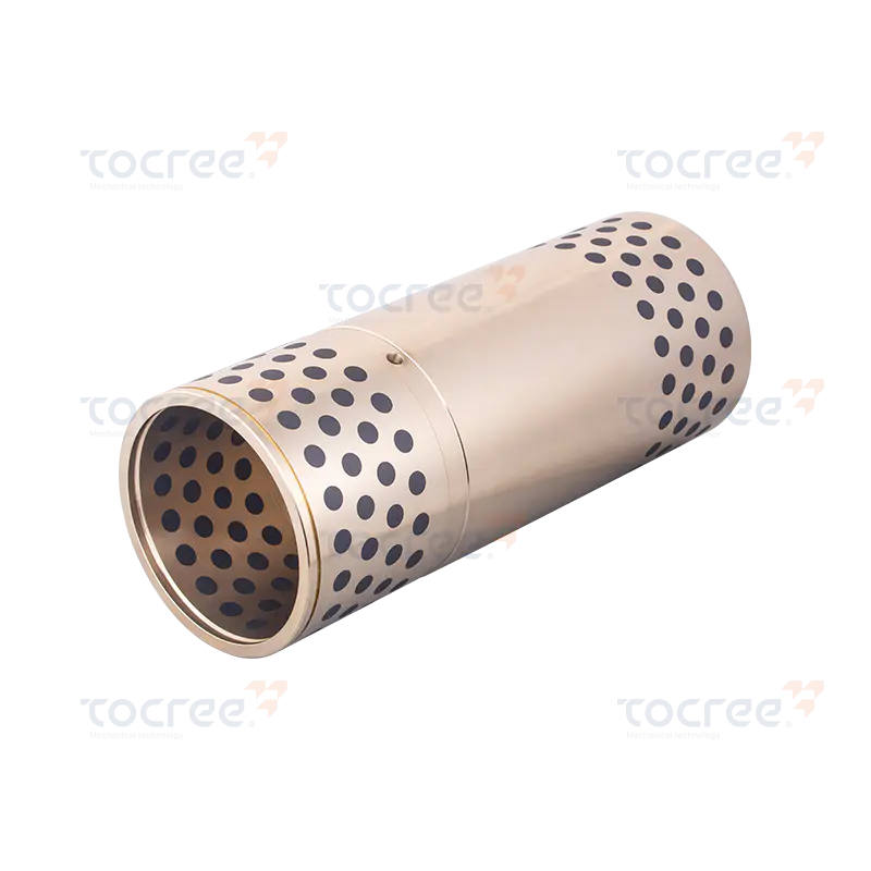
Material structure: Cast aluminum brass CuZn25Al6Fe3Mn3, with graphite insert. Application features:...
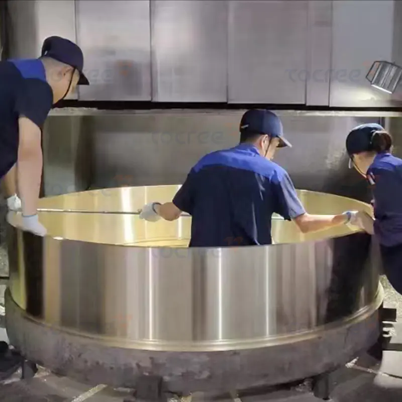
This high-performance brass single flange sleeve is specially designed for large industrial bearings...
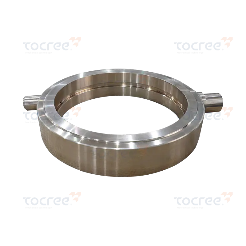
This copper-based oil drain ring is made from high-quality tin bronze through precise processing. It...
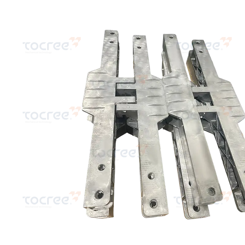
This aluminum alloy frame is specially designed to meet the application requirements of the vehicle....
Copyright © 2025 Jiashan Tocree Machinery Co., Ltd. All Rights Reserved.
Customized Copper Alloys Machinery Parts
